

Pressure Sensor Ifm PN2512
IFM CATEGORIES
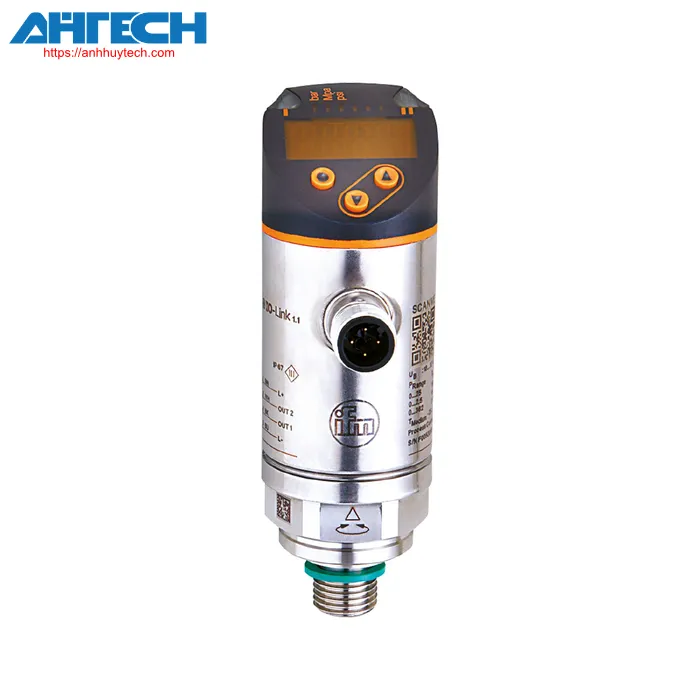
Pressure Sensor PN2512
Brand: Ifm
Product Code: PN-160-SEG14-MFRKG/US/ /V
- Dual switching outputs, with one customizable as IO-Link and the other as an analog output
- Red/green indicator for easy recognition of the acceptable range
- The process connection is adjustable for optimal alignment
- Features long-term stability due to robust overload protection
- Sturdy construction for application in demanding industrial settings
 Contact via Zalo
 Phone call
Product characteristics
| Total count of inputs and outputs | Count of digital outputs: 2; Count of analog outputs: 1 | |||
| Measuring span |
| |||
| Connection for process | screw connection G 1/4 with outdoor thread (DIN EN ISO 1179-2); internal thread: M5 | |||
| System | gold-plated terminals | |||
| Sensing element | ceramic capacitive force per unit area sensing element | |||
| Application | for commercial applications | |||
| Media | fluids and gases | |||
| Potentially appropriate for | usage in gases at force per unit areas > 25 bar available only upon request | |||
| Intermediate temperature value[°C] | -25...80 | |||
| Minimum force per unit area before bursting |
| |||
| Pressure classification |
| |||
| Vacuum strength |
| |||
| Kind of force per unit area | relative force per unit area | |||
| Response duration[ms] | < 1.5 | |||
| Programmable delay time dS, dr[s] | 0...50 | |||
| Damping process parameter dAP[s] | 0...4 | |||
| Damping for the analog output dAA[s] | 0...4 | |||
| Max. response duration for analog output[ms] | 3 |
Software / programming
| Configuration options | hysteresis / threshold; typically open / default closed; activation/deactivation delay; damping; display module; current/voltage output | ||||||||
| communication interface | IO-Link | ||||||||
| Mode of transmission | COM2 (38,4 kBaud) | ||||||||
| IO-Link version | 1.1 | ||||||||
| SDCI specification | IEC 61131-9 | ||||||||
| Configurations | Intelligent Sensor ED2: Digital Measurement Sensor (0x000A), Identification and Fault Detection (0x4000) | ||||||||
| SIO mode | yes | ||||||||
| Necessary master port category | A; (when pin 2 not connected: B) | ||||||||
| Minimum process cycle duration[ms] | 3 | ||||||||
| IO-Link force per unit area accuracy[bar] | 0.05 | ||||||||
| IO-Link cyclic process data |
| ||||||||
| IO-Link acyclical functions | application-specific label | ||||||||
| Supported DeviceIDs |
| ||||||||
| Note |
| ||||||||
| Measuring span |
| ||||||||
| Setpoint SP |
| ||||||||
| Reset threshold rP |
| ||||||||
| Analog initiation point |
| ||||||||
| Analog endpoint |
| ||||||||
| Minimum difference between set point (SP) and reference point (rP) |
| ||||||||
| In increments of |
|
Inputs / outputs
| Total count of inputs and outputs | Count of digital outputs: 2; Count of analog outputs: 1 |
| Voltage for operation[V] | 18...30 DC; (to SELV/PELV) |
| Current draw[mA] | < 35 |
| Minimum insulation resistance[MO] | 100; (500 V DC) |
| Safety feature rating | III |
| Reverse polarity safeguard | yes |
| Activation delay time[s] | 0.3 |
| Built-in watchdog | yes |
| Overall count of outputs | 2 |
| Output response | output signal; analog output; IO-Link; (customizable) |
| Electrical engineering design | PNP/NPN |
| Count of digital outputs | 2 |
| Output feature | typically open / closed; (customizable) |
| Max. voltage drop at switching output DC[V] | 2 |
| Continuous current rating of the switching output DC[mA] | 250 |
| DC switching frequency[Hz] | < 500 |
| Total analog outputs | 1 |
| Analog current output[mA] | 4...20; (adjustable 1:5) |
| Max. capacity[O] | 500 |
| Analog voltage output[V] | 0...10; (expandable 1:5) |
| Minimum load resistance[O] | 2000 |
| Overcurrent protection | yes |
| Method of overcurrent protection | yes (momentary) |
| Overcurrent protection | yes |
| Precision of switch points/span>[% of the span] | < ± 0,4; (Turn down 1:1) |
| Reproducibility[% of the span] | < ± 0,1; (with temperature value fluctuations < 10 K; Turn down 1:1) |
| Characteristics variation[% of the span] | < ± 0.25 (BFSL) / < ± 0.5 (LS); (Turn down 1:1; BFSL = Best Fit Straight Line; LS = limit value setting) |
| Hysteresis variation[% of the span] | < ± 0,1; (Turn down 1:1) |
| Extended stability[% of the span] | < ± 0,05; (Turn down 1:1; per 6 months) |
| Temperature coefficient value for the zero reference[% of the span / 10 K] | < ± 0,2; (-0...80 °C) |
| Temperature coefficient value for the range[% of the span / 10 K] | < ± 0,2; (-0...80 °C) |
| Comments on the precision / variation | accuracy of switch points, linearity deviation per DNV GL: < ± 1%: < ± 1% |
| Surrounding temperature value[°C] | -25...80 |
| Temperature for storage[°C] | -40...100 |
| Safety feature | IP 65; IP 67 |
Download Specification for PN2512
Download PDFRELATED PRODUCTS
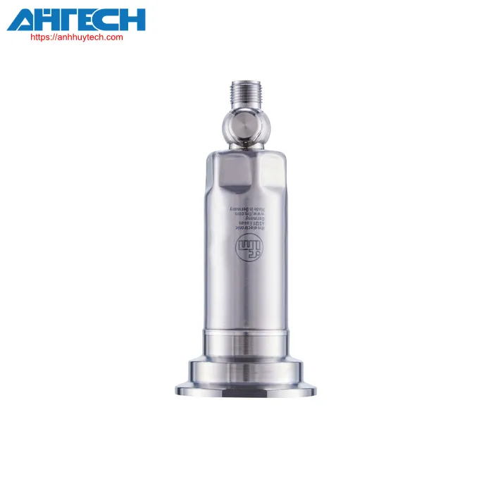
- Brand: IFM
-
Category Ifm Products:
Pressure Sensor -
Product Code:
PM-1,6BREZ01-E-ZVG/US
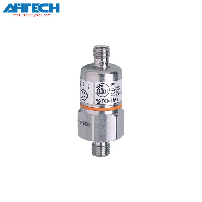
- Brand: IFM
-
Category Ifm Products:
Pressure Sensor -
Product Code:
PP-400-SBG14-QFPKG/US/ /V
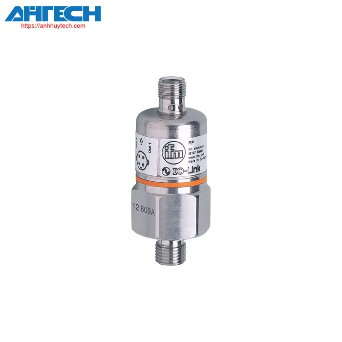
- Brand: IFM
-
Category Ifm Products:
Pressure Sensor -
Product Code:
PP-250-SBG14-QFPKG/US/ /V
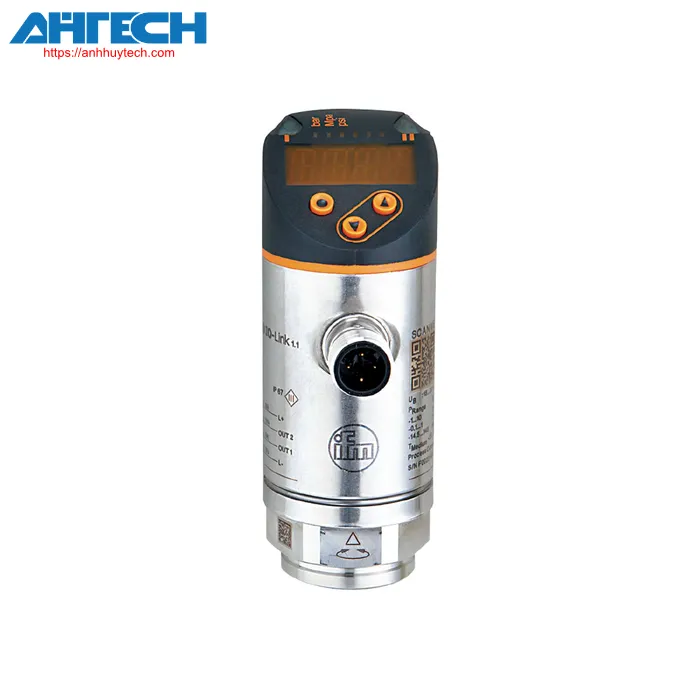
- Brand: IFM
-
Category Ifm Products:
Pressure Sensor -
Product Code:
PN-0-1BRER14-MFRKG/US/ /V
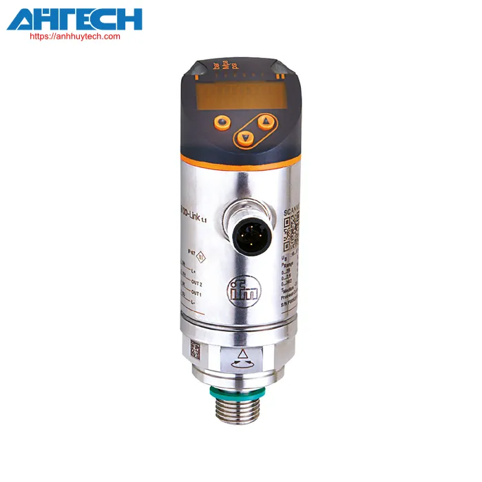
- Brand: IFM
-
Category Ifm Products:
Pressure Sensor -
Product Code:
PN-010-REG14-MFRKG/US/ /V
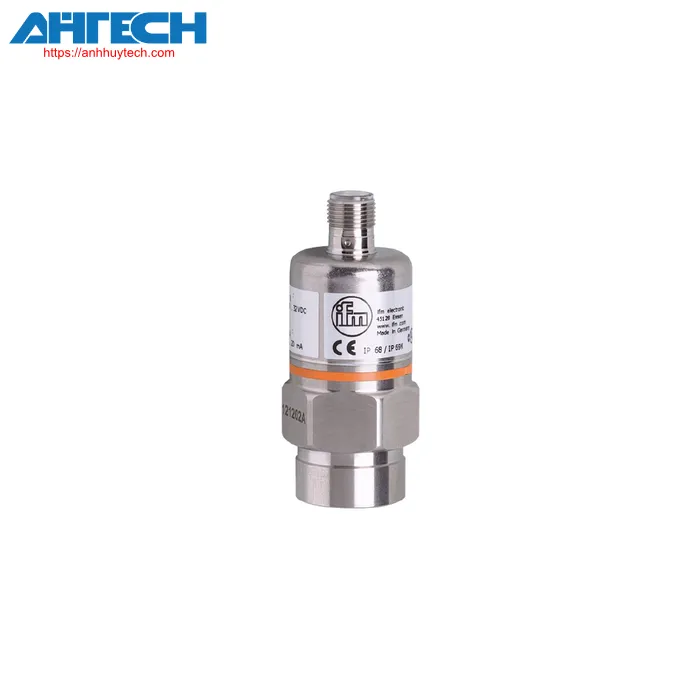
- Brand: IFM
-
Category Ifm Products:
Pressure Sensor -
Product Code:
PA-0-1-RBN14-A-ZVG/US/ /V
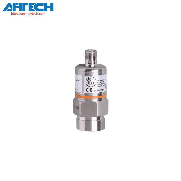
- Brand: IFM
-
Category Ifm Products:
Pressure Sensor -
Product Code:
PA-010-RBN14-A-ZVG/US/ /V
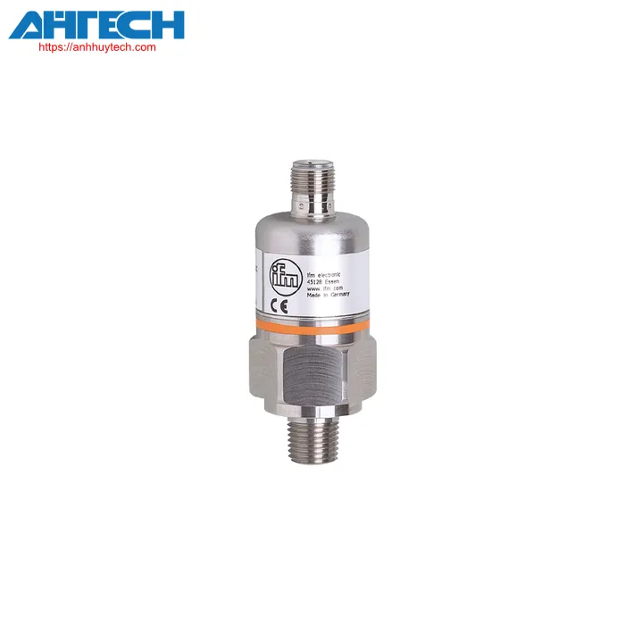
- Brand: IFM
-
Category Ifm Products:
Pressure Sensor -
Product Code:
PA-015PRBN14-A-ZVG/US/ /V
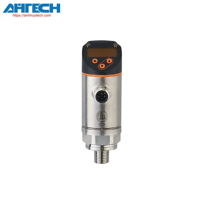
- Brand: IFM
-
Category Ifm Products:
Pressure Sensor -
Product Code:
PN-1-1BREN14-MFRKG/US/ /V
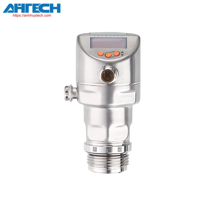
- Brand: IFM
-
Category Ifm Products:
Pressure Sensor -
Product Code:
PI-1-1BREA01-MFRKG/US/ /P