

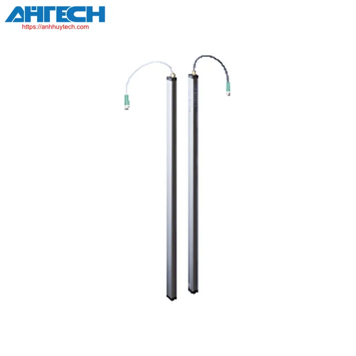
Photoelectric Sensor Pepperl+Fuchs LGM25
Pepperl+Fuchs Categories
 Contact via Zalo
 Phone call
Datasheet excerpt: Technical data of LGM25
| Item Specification | ||
|---|---|---|
| Measuring automation light grid with a beam separation of 25 mm, IO-Link interface, push-pull output, permanent cable equipped with M12 connector | ||
| Overall specifications | ||
|---|---|---|
| Operational sensing range | Standard : 0.3 ... 6 m | |
| detection range threshold | 7.5 m | |
| illumination source | IRED | |
| Illumination type | modulated infrared light at 850 nm | |
| field elevation | see Table 1, max. 3200 mm | |
| Beam intersection | Factory configuration: three beam crossing, can be disabled | |
| Beam suppression | adjustable max. 2 fixed suppressible light beams (blanking) | |
| Beam separation | 25 mm | |
| Beam count | see Table 1, max. 129 | |
| Operation mode | Emitter: Emitter power configurable in two settings | |
| imaging resolution | without beam overlap: 25 mm with beam crossover: 12.5 mm within 25% and 75% of the range |
|
| angle of opening | 10 ° | |
| Ambient light threshold | > 50000 Lux (when the external light source is positioned outside the opening angle) | |
| Parameters related to functional safety | ||
| MTTFd | 34 a | |
| task duration (TM) | 20 a | |
| Diagnostic Range (DC) | 60 % | |
| Indicators/operation controls | ||
| Operational status indicator | LED green: perpetually active - power-on Double pulse flashing (0.8 Hz) - low voltage detection flashing (4 Hz) - short circuit flashing with brief interruption (1 Hz) - IO-Link mode |
|
| Condition indicator | Emitter: Yellow indicator LED always on - high emitter power always off - low emitter power flashing (8 Hz) - fault indication Transducer: Yellow indicator LED: always active - object identified permanently off - no object recognized flashing (4 Hz) - dropping below operational reserve flashing (8 Hz) - fault indication |
|
| control components | Transducer: 2 tactile buttons for configuration | |
| Electrical parameters | ||
| Operational voltage | 18 ... 30 V DC | |
| Ripple | 10 % | |
| No-load input current | Emitter =: 50 mA Transducer: = 150 mA (in idle state without outputs) |
|
| Delay time prior to availability | see Table 1, max. 2.3 s | |
| Connection point | ||
| Type of interface | IO-Link ( pin 4 ) | |
| IO-Link revision | 1.0 | |
| Device ID | 1050369 ... 1050400 ( 0x100701 ... 0x100720 ) | |
| COM-Mode | COM2 (38.4 kBit/s) | |
| Minimum cycle time | 2.3 ms | |
| process data range | 16 bit | |
| SIO mode support | yes | |
| Input | ||
| Verification input | Deactivation of emitter with +UB or 0 V at pin 4 (transmitter) | |
| Input function | Input activation range starts at 1.6 m with +UB or 0 V on pin 2 (transmitter) Teach-In interface for parameter configuration on pin 8 (receiver) |
|
| Output | ||
| Stability fault indication output | Stability Control (SC) 1 PNP, featuring short-circuit protection and reverse polarity protection on pin 2 (receiver) | |
| Type of switch | Factory setting: dark mode enabled, switchable to light mode | |
| Output signal | Command interface: Pin 4 IO-Link interface C or utilized as switching output Q; 1 short-circuit protected, reverse polarity safeguarded push-pull output (receiver) Switch output: Pin 5 switching output Q; 1 short-circuit resistant reverse polarity safeguarded push-pull output (receiver) synchronized with pin 4 |
|
| activation threshold | Factory setting: The signal tracking for the threshold value is turned off, enhancing the optical resolution by up to 4 mm; can be switched to enable active signal tracking | |
| Switching voltage level | max. 30 V DC | |
| Switching capacity | max. 100 mA | |
| voltage loss | = 2 V DC | |
| commutation frequency | see Table 1, max. 135 Hz | |
| reaction time | see Table 1, max. 12 ms | |
| Timing feature | Post-delay adjustable from 0 ... 1.25 s in 5 ms increments (configuration through IO-Link only) | |
| Compliance | ||
| Communication interface | IEC 61131-9 | |
| Product specification | EN 60947-5-2 | |
| Certifications and approvals | ||
| Ingress protection rating | III ( IEC 61140 ) | |
| UL certification | cULus Certified | |
| CCC certification | CCC certification / marking not necessary for products rated ≤36 V | |
| Environmental conditions | ||
| Ambient temperature | -30 ... 60 °C (-22 ... 140 °F) | |
| Ambient storage temperature | -30 ... 70 °C (-22 ... 158 °F) | |
| Mechanical characteristics | ||
| Conductor cross-sectional area | min. 0.25 mm2 | |
| Housing length L | see Table 1, max. 3360 mm | |
| Protection等级 | IP67 | |
| Linkage | Emitter: connection cable featuring 4-pin, M12 x 1 connector, 330 mm overall length Transducer: connecting cable with 8-pin, M12 x 1 connector , 350 mm total length |
|
| Material | ||
| Housing | extruded aluminum profile, silver anodized | |
| optical surface | synthetic panell, polycarbonate | |
| Mass | see Table 1, max. 1750 g (per profile) | |
| Measurements | ||
| Width | 20 mm | |
| Depth | 30.5 mm | |
| Cable duration | max. 30 m | |
Download Specification for LGM25
Download PDF
RELATED PRODUCTS
- Brand: PEPPERL+FUCHS
-
Category:
Photoelectric Sensor -
Product Code:
- Brand: PEPPERL+FUCHS
-
Category:
Photoelectric Sensor -
Product Code:
- Brand: PEPPERL+FUCHS
-
Category:
Photoelectric Sensor -
Product Code:
- Brand: PEPPERL+FUCHS
-
Category:
Photoelectric Sensor -
Product Code:
- Brand: PEPPERL+FUCHS
-
Category:
Photoelectric Sensor -
Product Code:
- Brand: PEPPERL+FUCHS
-
Category:
Photoelectric Sensor -
Product Code:
- Brand: PEPPERL+FUCHS
-
Category:
Photoelectric Sensor -
Product Code:
- Brand: PEPPERL+FUCHS
-
Category:
Photoelectric Sensor -
Product Code:
- Brand: PEPPERL+FUCHS
-
Category:
Photoelectric Sensor -
Product Code:
- Brand: PEPPERL+FUCHS
-
Category:
Photoelectric Sensor -
Product Code:
Anh Huy Technical Services Company Limited
VAT NUMBER:3703261459
140B/1 Tran Quang Dieu, Phuong An Phu, Thanh pho Thuan An, Tinh Binh Duong, Viet Nam
[email protected]
+84.947.20.80.80